Evo 8 and Evo 9 turbo upgrade options

We now offer a 6 blade 56mm x 73 x 75mm billet extended tip compressor wheel for the Evo 8 and Evo 9 turbo chargers.  We can match the 56mm compressor wheel with a tdo6sl2R (54mm x 61mm 11 blade) or tdo6h4R (58mm x 67mm 11 blade) turbine. I pair this 56mm billet wheel with the tdo6sl2 for the first dyno testing. Im hoping to see great horsepower results out of it with the tdo6sl2R turbine.

So far we have only got test results for the tdo5hR 20g (cast wheel, unclipped turbine) in and evo 9 turbo. Our results proved 493 awhp and 560 hp to the crank @ 31 psi.  We have not gotten results for the billet wheels yet. These two turbo are leaving for testing tomorrow 6/19/13. Both turbos have tdo6sl2R turbine upgrades and evo 9 10.5 cm^2 turbine housings.

Evo 8 billet 7 blade 20g (52.6mm x 68mm x 71mm) on the left.  Evo 8 56mm x 73mm x 75mm billet wheel upgrade on the right.

Evo 8 billet 7 blade 20g (52.6mm x 68mm x 71mm) on the left.
Evo 8 56mm x 73mm x 75mm billet wheel upgrade on the right.

For a reference on what to compare the 56mm turbo to our competitors, the fp Red has a compressor wheel approx (56mm x 75mm) and it uses a 58mm x 67mm turbine tdo6h4R shaft.  We can offer the tdo6h4R turbine, but the evo 9 turbine housing is so large that we were not concerned about picking up additional airflow on the turbine side. We were really impressed with how effective evo 9  turbine housing minimizes back pressure in the turbine housing at higher boost levels and higher rpm.

We also can build these turbo chargers with a billet 25g compressor wheel (60.5 mm x 78mm). We have seen kinugawa use a tdo6sl2R turbine but I strongly recommend the tdo6h4R turbine, because the tdo6sl2R turbine is so small compared the to the size of the 25g.  The tdo6sl2R turbine will never be able to support the flow of the 25g compressor wheel and you would be better off with a tdo6sl2R 20g over the tdo6sl2R 25g.  This is why we recommend using wheels close in flow rates.

You will be happy to know that Turbo Lab takes very good care of its customers when it comes to pricing. Unfortunately we can’t offer brand new evo 8 and evo 9 turbo chargers to build, so we buy used ones to build and stock on our shelf.  If you don’t have a core turbo charger we can just sell you a turbo charger that we have modified for your vehicle. The cast 20g compressor upgrade with rebuild is $400 and with billet wheel $550. The Evo 8 and Evo 9 rebuild and upgrade to the tdo6sl2r/20g billet compressor wheel or tdo6sl2r/56mm billet compressor wheel is 700$ with a core (parts and labor included).  If you want to upgrade to the tdo6h4R turbine, the cost is an additional $100.

If you send an evo 9 turbo in or if you are buying an evo 9 turbo from us and you plan to t0 upgrade to the billet 25g, we have the option of using an anti-surge compressor housing. The anti-surge compressor housings are only avaiable for the evo 9 turbo chargers because of the larger diameter of the bearing housing and compressor housing. The total cost of the build for an evo 9 25g, with tdo6h4R turbine, and anti-surge compressor housing is $800 with a core.

If you don’t have a core, you can purchase one from us.

We hope to hear from you soon.

ko3 ko4 ko6 Turbo upgrade for audi a4, volkswagen gti, Chevy cobalt, pontiac sky, mazda 3

Turbo Lab's ko3 ko4 ko6 50mm x 61mm billet compressor wheel upgrade.

Turbo Lab’s ko3 ko4 ko6 50mm x 61mm billet compressor wheel upgrade.

Turbo Lab now offers a 50mm x 61mm billet compressor wheel upgrade for ko3/ko4/k06 turbo chargers. The craftsmanship of the ko3 turbo upgrade is intense because it involve very precise machine skills to make this turbo build possible. The new inlet of the compressor housing becomes a massive 2.375″ outside diameter which is flared out for more air flow and better spool capability.


This turbo upgrade also utilizes the biggest turbine available for the k series turbo which is the 44.5 mm x 50 mm ko4/ko6 turbine. We can also offer turbine clipping for this turbo to help with even more flow capability.  If you have a ko4 or ko6 from factory your turbo would just need a simple compressor upgrade to build what you see here. Keep in mind not all of the compressor housings are the same, if your wondering why this compressor housing doesn’t look like yours, the reason why is because its probably not the same housing, but as long as your turbo is a ko3-k06 we can offer this 50mm x 61mm compressor upgrade.

981398_4658788943869_980542521_oThe most common cars that run the Borg Warner k series turbos are the audi a4, voltswagen jetta and gti, chevy cobalt, pontiac sky, and mazda 3.  We are proud to now offer this turbo, though we have not gotten any result of what it will do, we can predict by its size that it should be able to 320-350whp of airflow.  We are even more excited to upgrade the twin turbos on an audi a6 next to see what we can get out of them. With two of these turbo upgrades on an audi a6 2.7 v6, we are expecting to see 500-600 hp of air flow.

Understanding I Why Turbine housings Crack

Turbine housings can crack from an improper tune which causes high EGT (exhaust temperatures). Another reason why they crack is due to improper cool down of the turbocharger. It is important to let the automobile idle for a few minutes to let the oil recirculate through the turbo charger to remove the heat from the turbo charger. This cool down period is even more important in the winter time. During this idle time exhaust system will also release heat. Turbine housings cracking is not covered by OEM manufactures due to falling under the category of miss use of the turbocharger.  This is also something that is out of our control.

Most manufactures use a nickel additive in the turbine housings, the help prevent cracking of the turbine housing. This significantly reduces the chance of the turbine housing cracking. However Often the turbine housing will still crack on sharp edges in the turbine housing.

Some companies have also used pure stainless steel turbine housings, which also reduces the possibility of the turbine housing cracking. However, sharp edges of the turbine housing still tend to crack. A way to try and prevent cracking is to use a porting tool and sand the sharp edges of the turbine housing smooth, which I do to the best of my ability. However I have no control over improper cool down of the turbocharger.

Precision Turbo thrust bearing failures


Pte thrust bearing failure

Pte thrust bearing failure

We are seeing more and more thrust bearing failures on PTE turbos. Even though PTE uses the same rebuild kits as TO4E garrett, Comp Turbos, and some turbonetics, they are failing because pte is using a steel thrust bearing.  The steel is stronger but it doesn’t not dissipate the heat as well as the brass.  All turbo manufactures that make turbochargers trucking companies, automotive manufactures, machinery, etc use brass thrust bearings.  Some aftermarket kits use steel thrust bearings, but we highly recommend not using them.  The result of the failure is that turbine shaft welds itself to the thrust collar because so much heat is generated do to the metal thrust bearing.  Changing out the metal thrust bearing with a brass one will prevent these failures. The failure usually happens within 2,000 miles of use. The metal thrust bearings are very sensitive if they are not oiled properly, with the correct oil weigh and oil pressure. I recommend changing out the metal thrust bearing with a brass bearing, mainly because the brass bearing removes heat better and will prevent the turbine shaft from fusing itself to the thrust collar.

Our recommended 360 degree brass thrust bearing for garrett, PTE, Comp, and turbonetics to4e turbos.

Our recommended 360 degree brass thrust bearing for garrett, PTE, Comp, and turbonetics to4e turbos.


What happens is the heavy rotating assembly pulls on the rotating assembly and loads the thrust system. The higher the boost level, the higher the thrust load. The friction from the steel-on-steel thrust system causes heat to build rapidly when the improper oil is used, and the result is the thrust washer (which is the thinnest part of the entire thrust system) overheats and explodes causing the failure.  The use of a steel thrust plate is not necessary though I have seen that Force Performance had used some steel thrust bearings in the past as well.  From what I could tell from the turbos i received for rebuild, fp used started out with brass thrust bearings, then changed to steel bearings, and then changed back to brass thrust bearings.  The steel bearings are causing more failures when they were meant to help with durability. As the old saying goes “If its not broke don’t fix it.” You don’t need to use a steel thrust plate on a turbo with a thrust system that is well-designed in order to gain necessary durablilty, proven by BW, Holset, Mitsubishi, and Garrett.  However it is necessary to use a 360 degree thrust bearing for performance applications.   It is also very important to use and upgraded thrust bearing kit for the mitsubishi turbo chargers that are using an upgraded rotating assembly. The upgraded thrust bearing kits come with a thicker thrust collar, thrust spacer, and 2 oil ports on the thrust bearing for maximum strength. We have had no failures from manufacture defects from the parts that we use in our turbos.  We highly recommend people that want to build their own turbos to buy the correct kits from us, so you know you will have the reliability and strength of a Turbo Lab built turbo. You can order the proper rebuild kit here:

Garret TO4E 360 degree rebuild kit P/N 408105-5285 on Square Market

Steel thrustbearing from an fp green

Steel thrustbearing from an fp green

MHI upgraded thrust bearing  with thicker thrust spacer

MHI upgraded thrust bearing with thicker thrust spacer

       Another cause of thrust bearing failures is contaminates clogging up the thrust bearing oil feed hole(s), but that is never a manufacture defect. Most of the time contaminates clogging up the oil feed holes is user error from the oil not being changed on a regular basis or the own put on a dirty junk yard part that has engine oil that passes through it and carries the dirt through the whole engine including the turbo.
More info on Garrett turbos can be found at here
We Also offer a Standard rotation rebuild kit for MHI turbos here:

MHI 16g, 20g, FP turbo rebuild kit on Square Market

We offer a Reverse rotation rebuild kit here:
Evo9 turbo rebuild kit reverse rotation on Square Market


Choosing turbine housings

turbine housing

Often when building custom turbos people will want to make a good deal of power and still have decent spool time. The best way to accomplish great spool up on a higher flowing turbo is to put a smaller turbine housing on it. A good example is taking a holset hx40 and replacing the factory .89 a/r housing and replacing it with a bep .55 a/r bep housing for a dsm.  The hx40 with the bep housing will be limited to 550-600 hp range instead of the 700 hp mark that people have made with the .89 a/r, but the spool time will increase which makes the turbo more streetable.  Another good example is having us machine a garrett t3 .63 a/r turbine housing to fit an hx35 or hx40. This will limit what this turbo is capable of flowing, but it will bring down the capable flow rates of the turbo down to size with a smaller engine to help spool time and over all efficiency. A good example is if you pair an hx35 with a 16 cm^2 turbine housing with a 2.0 liter 4 cylinder motor. If the car can ever spool that turbo up it will make huge amounts of power, but it wont start seeing boost until around 5,500 rpm in 3rd gear. If you had us machine a .63 a/r turbine housing for the same hx35, then the spool time will be moved to the 3,000-4000 rpm range depending on your boost level and it will still be capable of 450-500 hp.  The turbine housing choice that is best for your application depends on the displacement and number of cylinders of the engine that you are turbo charging.  Another deciding factor is what kind of power you are looking to make and drivability. When choosing a turbine housing you are sacrificing capable horsepower for spool time.

Often people will ask: should I go t4 or should I go t3 for my exhaust housing? This best way to answer this is by asking your self what kind of HP you want to make, and what kind of spool time you want to see. Also keep in mind the motor that you are using too. If its a 2.0 and your trying to make 450 awhp and you want to have decent spool time, I would recommend that you choose a t3 .63 a/r turbine housing or close. If you are turbocharging a 5.0 v8, the motor is naturally flowing 5 liters of air, so it makes sense that you need to used a larger turbine turbine housing in the t4 format to avoid choking the flow of the engine at higher rpm.  If you want decent spool time you want to put a turbo on the car that has flow rates close to the engine. If you use a turbo that flow less than the motor at 6500 rpm, then at 6500 rpm at wide open throttle you will feel the car stop pulling because the motor is having a hard time flowing more air because turbo turbo is limiting the flow. The fix for this would be to upgrade the turbine housing or the turbine wheel and compressor wheel. A good example is an evo 9 20g that we built that made 493 awhp, but the car choked at 6500. We never upgraded the turbine shaft of this turbo so the measurement were 52mm x 68mm for the compressor wheel and 49mm x 55.6mm for the turbine wheel. The reason the car was capable of 493whp, is because the turbine housing is twin scroll and 10.5 cm from the factory. If we wanted to help the car pull harder in the higher rpm range, we upgrade the turbine shaft to a tdo6h4R (58mm x 67mm) or tdo6sl2R turbine (54mm x 61mm). Though both turbines would help the turbo pull to redline, the tdo6sl2 turbine would be the best for spool time and the tdo6h4R turbine would be better for more power. The main reason why we upgrade the turbine wheels in most turbos that we build is because it is very limited for the turbine housing sizes for factory cars. In most cases there are no upgraded turbine housings, so we upgrade the turbine shafts as an alternative, which works better if your trying to retain some of your spool time.

There is not  a direct conversion for an A/R to cm^2 estimate but this chart works well for an estimate. 

Turbine housing

A/R to cm^2 estimate

6 cm2 = 0.41 A/R

7 cm2 = 0.49 A/R

8 cm2 = 0.57 A/R

9 cm2 = 0.65 A/R

10 cm2 = 0.73 A/R

11 cm2 = 0.81 A/R

12 cm2 = 0.89 A/R

14 cm2 = 0.97 A/R

15 cm2 = 1.05 A/R

16 cm2 = 1.13 A/R

17 cm2 = 1.29 A/R

19 cm2 = 1.37 A/R

Billet Compressor Wheel

bullet2 billet wheel

       With more and more billet compressor wheels on the turbo market than ever, people raise the question: Is it worth it? The truth is it depends on the billet wheel. The first reason for billet wheels was for making a light weight compressor wheel out of a solid piece of aluminum for spool time and over all flow. PTE has the lightest billet compressor wheels on the turbo market today, because they actually remove the most metal from the wheel than any other companies, but they are commonly known for thrust bearing problems which i will explain in another article. Our extended tip compressor wheels are capable of generating more air flow because of the higher blades, however the extended tip wheels are heavier than the regular cast wheels by about 10 grams, but they are worth it because of the wheel capturing more air.  These wheels are machined with a 5 axis endmill which precisely cuts the wheel from a solid piece of aluminum.  These wheels range from 120 to 400$. The batmowheel billet wheel has proved to flow well, the wheel was derived from GE jet engines from air planes. This shape of the wheel was created to allow air to easily flow behind each blade in front of it. The tips are also extended to grab extra air, just like GE’s jet engines.


 billet wheels


The reason for changing the number compressor blades is to determine at what rpm the turbo will flow the most air. The less number of blades the more air it will flow at higher boost levels compared to a compressor wheel with more blades. A compressor wheel with more blades will flow very well at higher boost levels(~30 psi) but will not flow as well at lower boost levels. The Lower the blade count on the compressor wheel will help the turbo flow more air than the same compressor wheel with more blades. The more blades on a compressor wheel will help the compressor wheel have a peak flow at lower boost levels (20-25 psi). However some companies have started to make compressor wheels taller to allow a compressor wheel with more blades to grab more air and to flow better at higher boost levels as well. You will see taller 11 blade compressor wheels in the GTX series compressor wheels which are created by garret. The higher the blade count also helps with spool time, because it captures more air at lower rpm of the turbo.  The choice of compressor wheel depends on the what your goals are as far as spool time and the boost level that you plan to run. google622582fe1d69e3ee

What to do to Help your Turbo Last Longer

Turbo Failure

       To get the most life out of your turbocharger it is very important to understand how turbochargers fail. The most common reason for failure is the seals leaking in the turbocharger because of wear.  Shutting your engine off immediately after hauling heavy loads in your truck or doing hard pulls in your car, causes the oil on the turbine to dry up. The next time your start the vehicle the turbocharger will experience a dry start and this is what causes the wear.  If you allow your engine to idle after putting your vehicle under extreme loads, the engine oil will circulate and take away the heat in the engine and turbo charger. The recommended idle time is 1 to 5 minutes depending on how hard you push your car or trucTo get the most life out of your turbocharger it is very important to understand how turbochargers fail. The most common reason for failure is the seals leaking in the turbocharger because of wear.  Shutting your engine off immediately after hauling heavy loads in your truck or doing hard pulls in your car, causes the oil on the turbine to dry up. The next time your start the vehicle the turbocharger will experience a dry start and this is what causes the wear.  If you allow your engine to idle after putting your vehicle under extreme loads, the engine oil will circulate and take away the heat in the engine and turbo charger. The recommended idle time is 1 to 5 minutes depending on how hard you push your car or truck.

Lack of Lubrication

        The next common  cause of failure of your turbo is running to thin of oil. The thicker the oil the better the protection in higher heat conditions. The thinner oil is for extreme cold conditions. The oil weight for your engine is just as important for your turbo, and you should go by what the manufacture recommends. For race car applications, its important to go with racing oil.  I have one customer that lives in the  below  0°F temperature, and he would put 5w 30 motor oil in it in the winter, which is fine for those temperatures, but when summer came around every year, his turbo would fail.  The manufacture of his turbo recommends 10w 30 year round.

How does oil contamination damage turbos?

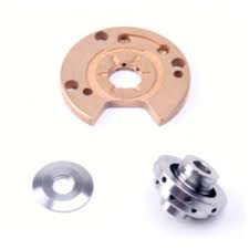
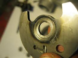
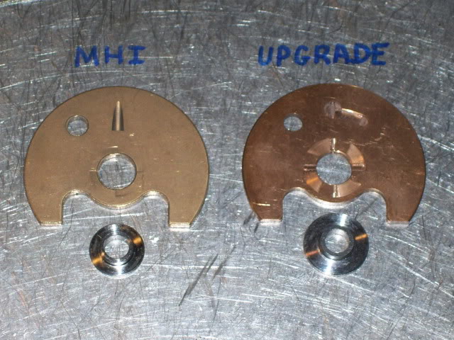
       Oil contamination is another common cause of failure of turbochargers. Oil contamination can be carbon, sludge, metal flake, or dirt which gets in the turbocharger and clogs up the thrust bearing and causes in and out play, or locks up a bearing and shaft and causes the shaft to break. The most common problem of oil contamination is metal flake and carbon clogging up the thrust bearing of a turbo. I have also seen parts of stripped threads inside a thrust bearing.  To help prevent oil contamination you can run the oil pressure from the oil filter housing directly to the turbocharger. Most contaminates in the oil are found in the cylinder head, by taking oil straight from the oil filter you are taking the cleanest oil available and bypassing the cylinder head.  When a turbo blows oil it puts your engine and its components at high risk for failure, because the oil pressure become lower.  Also when the oil level gets to so low that the oil pressure becomes non-existant.     

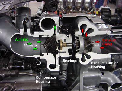
As turbochargers can operate at over 240,000 rpm and temperatures of 950°C, turbo bearings are under great stress. The turbine shaft and bearings rotate in a thin film of oil. Consequently any fault with the oil supply to the turbo means its bearings are likely to fail before the engine’s main bearings. Running a turbo without oil for five seconds is more harmful as a motor running without oil for five minutes. Since the turbo spins over 39 times faster than an engine, you will see a turbo fail 39 times soon than the engine. When a turbo blows oil it puts your engine and its components at high risk for failure, because the oil pressure become lower.  Also when the oil level gets to so low that the oil pressure becomes non-existant.  When a turbo is leaking oil, it also is causing a drop in oil pressure to the rest of the engine. This concept can be compared to a water hose being sprayed, if you poke a hole in the hose, the water will still be sprayed out of the hose but the pressure is much lower.

.      While it is important to check the engine oil pressure meets the manufacturer’s specifications, it is even more critical that the oil feed lines to the turbo are clean and clear, so you are certain they can supply uncontaminated oil, at the correct pressure. Contaminated or dirty oil will scratch or score the bearings, leading to rapid wear and ultimately, turbocharger failure.  95% of turbo failures are because of problems with oil starvation, oil contamination or foreign object damage.


 What causes contaminated oil?

       A blocked, damaged oil filter, carbon build-up in the engine, engine parts transfer over from a blown engine, and accidental contamination of new oil during servicing.such as a cylinder head are all often causes of repeated oil contamination causing even new turbo chargers to blow oil immediately after install. This can rapidly contaminate even new oil.  On some vehicles, the oil bypasses the oil filter above 4500 rpm to provide better oil flow to the engine. Another type of oil contamination is gasoline or coolant. Having gasoline in the oil is often caused from worn spark plugs not burning the fuel off or from acids that build up in the oil from use causing premature wear from not changing the oil on time.  Coolant in your engine oil is just as damaging as pouring water in your engine oil and expecting the water to lubricate the engine parts. The coolant in the engine can cause the engine or turbo charger to hydro-lock.

Preventing turbo failure

• Always use fresh oil, the correct oil weight, and new oil filters as recommended by the engine manufacturer when installing a new turbo. We do not recommend using an inline filter in the oil feed line of the turbo charger because it can clog and cause problems, the best way is to run your oil feed line straight a location where oil has just pass through the oil filter. Often if there is something wrong with the motor’s oil pressure, regardless if the turbo that you install is good, it will blow oil.  Clean or replace oil feed and return lines to eliminate any carbon deposits or sludge that can enter the turbo or restrict the oil flow to the bearings. Before installing a new turbo, find out what caused the first turbo to fail or you risk the replacement turbo failing too.

       Turbo Lab supplies remanufactured replacement turbochargers, made by the original manufacturers to the highest quality standards. Though we confidently guarantee them, our standard warranty does not cover turbocharger failure caused by oil contamination or lack of oil.


What you need to know when upgrading your turbo

turbo_cutaway

       It is very important to know the basics of how a turbocharger works as well as what you are trying to achieve before you send your turbo in for upgrading.  The most important concept is to understand is that you want to build a turbo that has a compressor and turbine wheel with very similar flow rates. To achievethis, the compressor and turbine wheels should have measurements that are very close in size. The inducer of the compressor wheel and exducer of the turbine wheel are the measurements you want close in size. turbo measurements2 The inducer is the measurement of the wheel where the air enters, and the exducer is the measurement of where the air exits. Having less blades on the turbine wheel will help increase flow for a turbine shaft that has a limited measurement. A good example is a 20T compressor upgrade that measures 50 mm x 61 mm, but the biggest turbine upgrade available is the tdo4HL turbine which measures 45.6 mm x 52 mm. The tdo4HL turbine is offered in 12 blade from factory, however we can offer it in 11 blade, and I have also seen it offered in 9 blade too. The 50 mm 20T would have surge issues with the small turbine in 12 blade form, but when the 11 or 9 blade are used, the flow rate of the turbine is more closely match to the 50 mm compressor wheel which being a 45.6mm wheel. Turbine clipping offers the same effect as going with less blades, but instead of going with less blades, the blades are trimmed back to all for more air flow to pass by the turbine wheel. It is always better to go with a turbine that is closer in size to the compressor wheel if it is possible, but it is not always possible. When trying to match a turbine wheel to a compressor wheel that you have already chosen and the inducer measurements of the compressor wheel are inbetween the sizes of two different turbine upgrade sizes and you cant decide which one to go with, always go with the bigger turbine shaft. Turbos work better with an oversized turbine shaft than an oversized compressor wheel. A turbo with a bigger turbine exducer measurement will help prevent surge and support the flow of the smaller compressor rather than using a smaller turbine that will choke it. A good example is if your using a 56mm compressor wheel and the turbine choices are a tdo6h 58mm x 67mm and tdo6 55mm x 61mm, then go with the tdo6h turbine, or you could go with a tdo6 turbine that is clipped or has 11 blades instead of 12.


Boost Control Explained


       internalwg2Boost creep– Boost creep is caused when a free flowing exhaust system is put on a turbo charged car. When revving out to higher rpms your boost pressure(psi) will rise as your rpms of the motor rise. This happens because the waste gate passage can not flow enough air to by pass the turbo to control the boost efficiently. The reason why this happens when you change out the exhaust to a free flowing exhaust is because you the smaller exhaust provided back pressure which caused resistance to flow air passed the turbine wheel.


External WG

How to fix this: You can port the waste gate flapper area and add a bigger flapper valve to help prevent boost creep, but the best way is to go external waste gate and select the appropriate waste gate spring for the boost level that you plan to run. We find that it works best that the wastegate spring base pressure should be half or more than the boost pressure that you plan to run. So if you are running 30 psi, then you should have a 15 psi wastegate actuator.  The problems with porting the flapper hole and adding a bigger flapper is that it makes it harder to run higher boost levels. Dsm guys will see that there boost level will spike to their set boost level (lets say 20 psi), then when their rpms increase the flapper valve will have a hard time closing, because of the increased surface area of the bigger flapper valve in combination with the waste gate base spring pressure being to low, which makes the flapper struggle to shut to control the massive amount of air pressure that is coming through the turbine housing. When the valve is having a hard time closing it is releasing more pressure out of the turbine housing than it is supposed to their for even though your boost level is set to 20 psi it will fall off to 16 psi and hold a lower boost level to redline. The best way to go is to go external waste gate.